
Deploy a VPX high-availability pair with external static IP address on the Google Cloud Platform
You can deploy a VPX high-availability pair on GCP using an external static IP address. The client IP address of the primary node must be bound to an external static IP address. Upon failover, the external static IP address is moved to the secondary node for traffic to resume.
A static external IP address is an external IP address that is reserved for your project until you decide to release it. If you use an IP address to access a service, you can reserve that IP address so that only your project can use it. For more information, seeReserving a Static External IP Address。
For more information on HA, seeHigh Availability。
Before you start
Read the Limitation, Hardware requirements, Points to note mentioned inDeploy a Citrix ADC VPX instance on Google Cloud Platform。This information applies to HA deployments also.
- EnableCloud Resource Manager APIfor your GCP project.
Allow full access to all Cloud APIs while creating the instances.
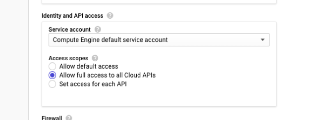
Ensure that the IAM role associated with your GCP service account has the following IAM permissions:
REQUIRED_INSTANCE_IAM_PERMS = [" compute.addresses。use", “compute.forwardingRules.list”, “compute.forwardingRules.setTarget”, “compute.instances.setMetadata” "compute.instances.addAccessConfig", "compute.instances.deleteAccessConfig", "compute.instances.get", "Compute.instances.list", "compute.networks.useExternalIp", "compute.subnetworks.useExternalIp", “compute.targetInstances.list”, “compute.targetInstances.use”, "compute.zones.list", ]If you have configured alias IP addresses on an interface other than the management interface, ensure that your GCP service account has the following extra IAM permissions:
"compute.instances.updateNetworkInterface"- If you have configured GCP forwarding rules on the primary node, read the limitations and requirements mentioned inForwarding rules support for VPX high-availability pair on GCPto update them to new primary on failover.
How to deploy a VPX HA pair on Google Cloud Platform
Here’s a summary of the HA deployment steps:
- Create VPC networks in the same region. For example, Asia-east.
- Create two VPX instances (primary and secondary nodes) on the same region. They can be in the same zone or different zones. For example Asia east-1a and Asia east-Ib.
- Configure HA settings on both instances by using the Citrix ADC GUI or ADC CLI commands.
Step 1. Create VPC networks
Create VPC networks based on your requirements. Citrix recommends you to create three VPC networks for associating with management NIC, client NIC, and server NIC.
To create a VPC network, perform these steps:
- Log on theGoogle console > Networking > VPC network > Create VPC Network。
- Complete the required fields, and clickCreate。
For more information, see theCreate VPC Networkssection inDeploy a Citrix ADC VPX instance on Google Cloud Platform。
Step 2. Create two VPX instances
Create two VPX instances by following the steps given inScenario: deploy a multi-NIC, multi-IP standalone VPX instance。
Important
Assign a static external IP address to client IP address (VIP) of the primary node. You can use an existing reserved IP address or create a new one. To create a static external IP address, navigate toNetwork interface > External IP, clickCreate IP address。
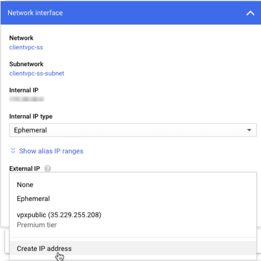
在故障转移之后,当旧主the new secondary, the static external IP address moves from the old primary and is attached to the new primary. For more information, see the Google cloud documentReserving a Static External IP Address。
After you’ve configured the VPX instances, you can configure the VIP and SNIP addresses. For more information, seeConfiguring Citrix ADC-owned IP addresses。
Step 3. Configure high availability
After you’ve created the instances on Google Cloud Platform, you can configure HA by using the Citrix ADC GUI for CLI.
Configure HA by using the GUI
Step 1。Set up high availability in INC mode on both the instances.
On theprimary node, perform the following steps:
- Log on to the instance with user name
nsrootand instance ID of the node from GCP console as the password. - Navigate toConfiguration > System > High Availability > Nodes, and clickAdd。
- In theRemote Node IP addressfield, enter the private IP address of the management NIC of the secondary node.
- Select theTurn on INC (Independent Network Configuration) mode on self nodecheck box.
- ClickCreate。
On thesecondary node, perform the following steps:
- Log on to the instance with user name
nsrootand instance ID of the node from GCP console as the password. - Navigate toConfiguration > System > High Availability > Nodes, and clickAdd。
- In theRemote Node IP addressfield, enter the private IP address of the management NIC of the primary node.
- Select theTurn on INC (Independent Network Configuration) mode on self nodecheck box.
- ClickCreate。
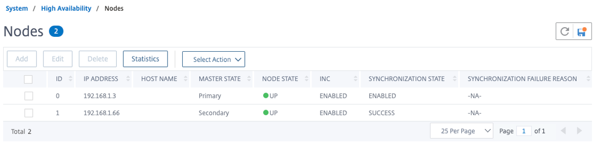
Before you proceed further, ensure that the Synchronization state of the secondary node is shown asSUCCESSin theNodespage.
Note
Now, the secondary node has the same log-on credentials as the primary node.
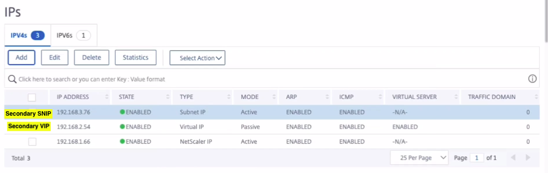
Step 2。Add Virtual IP address and Subnet IP address on both the nodes.
On theprimary node, perform the following steps:
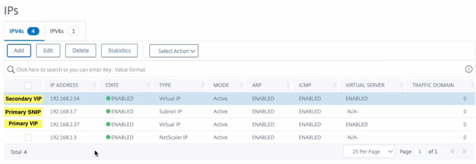
- Navigate toSystem > Network > IPs > IPv4s, and clickAdd。
- Add a primary VIP address by following these steps:
- Enter the internal IP address of the client-facing interface of the primary instance and netmask configured for the client subnet in the VM instance.
- In theIP Typefield, selectVirtual IPfrom the drop-down menu.
- ClickCreate。
- Add a primary SNIP address by following these steps:
- Enter the internal IP address of the server-facing interface of the primary instance and netmask configured for the server subnet in the primary instance.
- In theIP Typefield, selectSubnet IPfrom the drop-down menu.
- ClickCreate。
- Add a secondary VIP address by following these steps:
- Enter the internal IP address of the client-facing interface of the secondary instance and netmask configured for the client subnet in the VM instance.
- In theIP Typefield, selectVirtual IPfrom the drop-down menu.
- ClickCreate。
On thesecondary node, perform the following steps:
- Navigate toSystem > Network > IPs > IPv4s, and clickAdd。
- Add a secondary VIP address by following these steps:
- Enter the internal IP address of the client-facing interface of the secondary instance and netmask configured for the client subnet in the VM instance.
- In theIP Typefield, selectVirtual IPfrom the drop-down menu.
- Add a secondary SNIP address by following these steps:
- Enter the internal IP address of the server-facing interface of the secondary instance and netmask configured for the server subnet in the secondary instance.
- In theIP Typefield, selectSubnet IPfrom the drop-down menu.
- ClickCreate。
Step 3。Add IP set and bind IP set to the secondary VIP on both the instances.
On theprimary node, perform the following steps:
- Navigate toSystem > Network > IP Sets > Add。
- Add an IP set name and clickInsert。
- From theIPV4spage, select the virtual IP (secondary VIP) and clickInsert。
- ClickCreateto create the IP set.
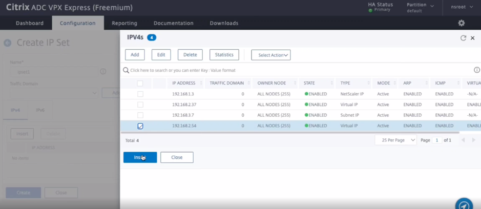
On thesecondary node, perform the following steps:
- Navigate toSystem > Network > IP Sets > Add。
- Add an IP set name and clickInsert。
- From theIPV4spage, select the virtual IP (secondary VIP) and clickInsert。
- ClickCreateto create the IP set.
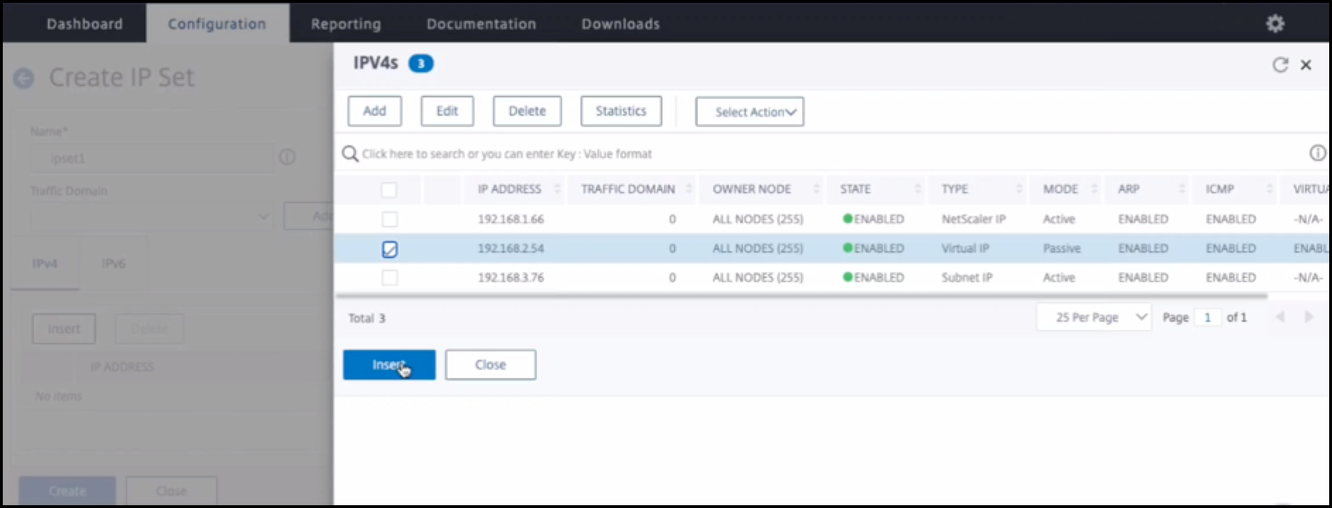
Note
IP set name must be same on both the instances.
Step 4。Add a load balancing virtual server on the primary instance.
- Navigate toConfiguration > Traffic Management > Load Balancing > Virtual Servers > Add。
Add the required values for Name, Protocol, IP Address Type (IP Address), IP address (primary VIP), and Port.
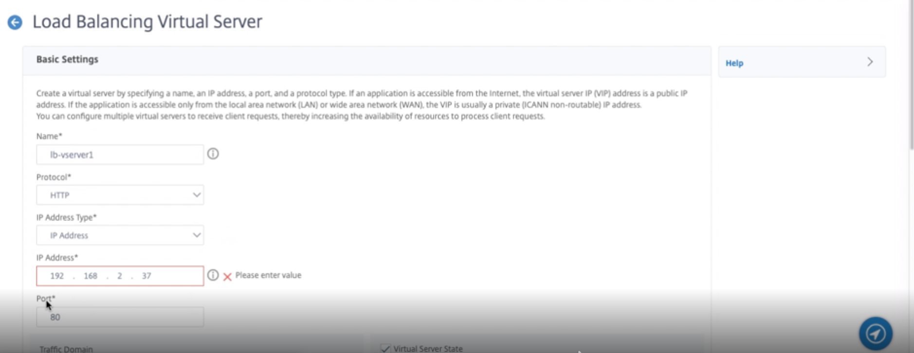
- ClickMore。Navigate toIP Range IP Set Settings, selectIPsetfrom the drop-down menu, and provide the IPset created inStep 3。
- ClickOKto create the load balancing virtual server.
Step 5。Add a service or service group on the primary node.
- Navigate toConfiguration > Traffic Management > Load Balancing > Services > Add。
- Add the required values for Service Name, IP Address, Protocol and Port, and clickOK。
Step 6。Bind the service or service group to the load balancing virtual server on the primary node.
- Navigate toConfiguration > Traffic Management > Load Balancing > Virtual Servers。
- Select the load balancing virtual server configured inStep 4, and clickEdit。
- In theService and Service Groupstab, clickNo Load Balancing Virtual Server Service Binding。
- Select the service configured in theStep 5, and clickBind。
保存配置。强制故障转移后,the secondary becomes the new primary. The external static IP of the old primary VIP moves to the new secondary VIP.
Configure high availability using CLI
Step 1。Set up high availability in INC mode in both the instances.
On the primary node, type the following command.
add ha node 1 -inc ENABLED On the secondary node, type the following command.
add ha node 1 -inc ENABLED sec_iprefers to the internal IP address of the management NIC of the secondary node.
prim_iprefers to the internal IP address of the management NIC of the primary node.
Step 2。Add Virtual and Subnet IPs on both the nodes.
On the primary node, type the following command.
add ns ip -type VIP add ns ip -type VIP add ns ip -type SNIP primary_viprefers to the internal IP address of the client-facing interface of the primary instance.
secondary_viprefers to the internal IP address of the client-facing interface of the secondary instance.
primary_sniprefers to the internal IP address of the server-facing interface of the primary instance.
On the secondary node, type the following command.
添加ns ip < secondary_vip > <子网>类型VIP添加ns ip -type SNIP secondary_viprefers to the internal IP address of the client-facing interface of the secondary instance.
secondary_sniprefers to the internal IP address of the server-facing interface of the secondary instance.
Step 3。Add IP set and bind IP set to secondary VIP on both the instances.
On the primary node, type the following command:
add ipset bind ipset On the secondary node, type the following command:
add ipset bind ipset Note
IP set name must be same on both the instances.
Step 4。Add a virtual server on the primary instance.
Type the following command:
add vserver -ipset Step 5。Add a service or service group on the primary instance.
Type the following command:
add service Step 6。Bind the service/service group to the load balancing virtual server on the primary instance.
Type the following command:
bind vserver Note:
To save your configuration, type the command
save config。不herwise, the configurations are lost after you restart the instances.
Step 7。Verify the configuration.
Ensure that the external IP address attached to the primary client NIC moves to the secondary on a failover.
- Make a cURL request to the external IP address and make sure that it is reachable.
On the primary instance, perform failover:
From GUI, navigate toConfiguration > System > High Availability > Action > Force Failover。
From CLI, type the following command:
force ha failover -fOn the GCP console, goto the Secondary instance. The external IP address must have moved to the client NIC of secondary after failover.
- Issue a cURL request to the external IP and ensure it is reachable again.