
Getting Started with Citrix ADC
Where Does a Citrix ADC Appliance Fit in the Network?
Deploy a Citrix ADC VPX instance
Install a Citrix ADC VPX instance on Microsoft Hyper-V servers
Install a Citrix ADC VPX instance on Linux-KVM platform
Prerequisites for Installing Citrix ADC VPX Virtual Appliances on Linux-KVM Platform
Provisioning the Citrix ADC Virtual Appliance by using OpenStack
Provisioning the Citrix ADC Virtual Appliance by using the Virtual Machine Manager
Configuring Citrix ADC Virtual Appliances to Use SR-IOV Network Interface
Configuring Citrix ADC Virtual Appliances to use PCI Passthrough Network Interface
Provisioning the Citrix ADC Virtual Appliance by using the virsh Program
Configuring a Citrix ADC VPX Instance on KVM to Use OVS DPDK-Based Host Interfaces
Deploy a Citrix ADC VPX instance on Microsoft Azure
Network architecture for Citrix ADC VPX instances on Microsoft Azure
Configure multiple IP addresses for a Citrix ADC VPX standalone instance
Configure a high-availability setup with multiple IP addresses and NICs
Configure a high-availability setup with multiple IP addresses and NICs by using PowerShell commands
Configure address pools (IIP) for a Citrix Gateway appliance
Upgrade and downgrade a Citrix ADC appliance
Solutions for Telecom Service Providers
Load Balance Control-Plane Traffic that is based on Diameter, SIP, and SMPP Protocols
Provide Subscriber Load Distribution Using GSLB Across Core-Networks of a Telecom Service Provider
Authentication, authorization, and auditing application traffic
Configuring authentication, authorization, and auditing policies
Configuring Authentication, authorization, and auditing with commonly used protocols
Use an on-premises Citrix Gateway as the identity provider for Citrix Cloud
Troubleshoot authentication issues in Citrix ADC and Citrix Gateway with aaad.debug module
-
-
-
-
-
Persistence and persistent connections
Advanced load balancing settings
Gradually stepping up the load on a new service with virtual server–level slow start
Protect applications on protected servers against traffic surges
Retrieve location details from user IP address using geolocation database
Use source IP address of the client when connecting to the server
Use client source IP address for backend communication in a v4-v6 load balancing configuration
Set a limit on number of requests per connection to the server
Configure automatic state transition based on percentage health of bound services
Use case 2: Configure rule based persistence based on a name-value pair in a TCP byte stream
Use case 3: Configure load balancing in direct server return mode
Use case 6: Configure load balancing in DSR mode for IPv6 networks by using the TOS field
Use case 7: Configure load balancing in DSR mode by using IP Over IP
Use case 10: Load balancing of intrusion detection system servers
Use case 11: Isolating network traffic using listen policies
Use case 12: Configure Citrix Virtual Desktops for load balancing
Use case 13: Configure Citrix Virtual Apps for load balancing
Use case 14: ShareFile wizard for load balancing Citrix ShareFile
-
-
-
-
Authentication and authorization
-
Configuring a CloudBridge Connector Tunnel between two Datacenters
Configuring CloudBridge Connector between Datacenter and AWS Cloud
Configuring a CloudBridge Connector Tunnel Between a Datacenter and Azure Cloud
Configuring CloudBridge Connector Tunnel between Datacenter and SoftLayer Enterprise Cloud
Configuring a CloudBridge Connector Tunnel Between a Citrix ADC Appliance and Cisco IOS Device
CloudBridge Connector Tunnel Diagnostics and Troubleshooting
This content has been machine translated dynamically.
Dieser Inhalt ist eine maschinelle Übersetzung, die dynamisch erstellt wurde.(Haftungsausschluss)
Cet article a été traduit automatiquement de manière dynamique.(Clause de non responsabilité)
Este artículo lo ha traducido una máquina de forma dinámica.(Aviso legal)
此内容已经过机器动态翻译。放弃
このコンテンツは動的に機械翻訳されています。免責事項
이 콘텐츠는 동적으로 기계 번역되었습니다.책임 부인
Este texto foi traduzido automaticamente.(Aviso legal)
Questo contenuto è stato tradotto dinamicamente con traduzione automatica.(Esclusione di responsabilità))
This article has been machine translated.
Dieser Artikel wurde maschinell übersetzt.(Haftungsausschluss)
Ce article a été traduit automatiquement.(Clause de non responsabilité)
Este artículo ha sido traducido automáticamente.(Aviso legal)
この記事は機械翻訳されています.免責事項
이 기사는 기계 번역되었습니다.책임 부인
Este artigo foi traduzido automaticamente.(Aviso legal)
这篇文章已经过机器翻译.放弃
Questo articolo è stato tradotto automaticamente.(Esclusione di responsabilità))
Translation failed!
Where does a Citrix ADC appliance fit in the network?
A Citrix ADC appliance resides between the clients and the servers, so that client requests and server responses pass through it. In a typical installation, virtual servers configured on the appliance provide connection points that clients use to access the applications behind the appliance. In this case, the appliance owns public IP addresses that are associated with its virtual servers, while the real servers are isolated in a private network. It is also possible to operate the appliance in a transparent mode as an L2 bridge or L3 router, or even to combine aspects of these and other modes.
Physical deployment modes
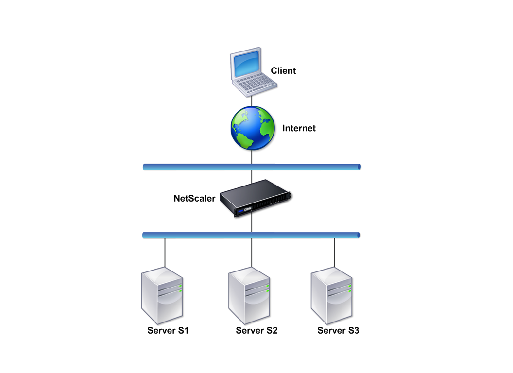
A Citrix ADC appliance logically residing between clients and servers can be deployed in either of two physical modes: inline and one-arm. In inline mode, multiple network interfaces are connected to different Ethernet segments, and the appliance is placed between the clients and the servers. The appliance has a separate network interface to each client network and a separate network interface to each server network. The appliance and the servers can exist on different subnets in this configuration. It is possible for the servers to be in a public network and the clients to directly access the servers through the appliance, with the appliance transparently applying the L4-L7 features. Usually, virtual servers (described later) are configured to provide an abstraction of the real servers. The following figure shows a typical inline deployment.
Figure 1. Inline Deployment
In one-arm mode, only one network interface of the appliance is connected to an Ethernet segment. The appliance in this case does not isolate the client and server sides of the network, but provides access to applications through configured virtual servers. One-arm mode can simplify network changes needed for Citrix ADC installation in some environments.
For examples of inline (two-arm) and one-arm deployment, see “Understanding Common Network Topologies.”
Citrix ADC as an L2 device
Citrix ADC设备功能作为L2设备is said to operate in L2 mode. In L2 mode, the ADC appliance forwards packets between network interfaces when all of the following conditions are met:
- The packets are destined to another device’s media access control (MAC) address.
- The destination MAC address is on a different network interface.
- The network interface is a member of the same virtual LAN (VLAN).
默认情况下,所有网络接口的成员a pre-defined VLAN, VLAN 1. Address Resolution Protocol (ARP) requests and responses are forwarded to all network interfaces that are members of the same VLAN. To avoid bridging loops, L2 mode must be disabled if another L2 device is working in parallel with the Citrix ADC appliance.
For information about how the L2 and L3 modes interact, seePacket forwarding modes.
For information about configuring L2 mode, see the “Enable and disable layer 2 mode” section inPacket forwarding modes.
Citrix ADC as a packet forwarding device
A Citrix ADC appliance can function as a packet forwarding device, and this mode of operation is called L3 mode. With L3 mode enabled, the appliance forwards any received unicast packets that are destined for an IP address that does not belong to the appliance, if there is a route to the destination. The appliance can also route packets between VLANs.
In both modes of operation, L2 and L3, the appliance generally drops packets that are in:
- Multicast frames
- Unknown protocol frames destined for an appliance’s MAC address (non-IP and non-ARP)
- Spanning Tree protocol (unless BridgeBPDUs is ON)
For information about how the L2 and L3 modes interact, seePacket forwarding modes.
For information about configuring the L3 mode, seePacket forwarding modes.
Share
Share
This Preview product documentation is Citrix Confidential.
You agree to hold this documentation confidential pursuant to the terms of your Citrix Beta/Tech Preview Agreement.
The development, release and timing of any features or functionality described in the Preview documentation remains at our sole discretion and are subject to change without notice or consultation.
The documentation is for informational purposes only and is not a commitment, promise or legal obligation to deliver any material, code or functionality and should not be relied upon in making Citrix product purchase decisions.
If you do not agree, select Do Not Agree to exit.